VENKATRAGHAVAN
A seasoned mechanical engineering leader with over 6 years of experience, I specialize in transforming innovative concepts into market-ready products. My expertise spans a variety of manufacturing processes, including injection molding, sheet metal fabrication, PCB interconnects, casting, and vacuum forming.
ANALYSIS OF A BASKETBALL BACKBOARD SYSTEM
The purpose of this project is to model a Hercules basketball backboard system and analyse the structure of the backboard and the supporting system when it is impacted by a professional basketball player who weighs approximately 200lbs.
ORIGINAL BASKETBALL BACKBOARD SYSTEM
In the NBA , it is observed that several times professional players tend to hold onto the rim of the basketboard and as a means of support or as they complete a dunk.
Assuming average weight of a power forward is approximately 200lbs and therefore a force equivalent to approximately 1000N is exerted by the player alone. Assuming that the player is dunking with a large momentum, the force is assumed to be 2000N ( approximately 2 times the players weight) .


FINITE ELEMENT MODEL
FE Model consists of 7 parts that are all homogenous solid elements.
1. Backboard
2. Rim
3. Arm1
4. Arm2
5. Bolt1
6. Bolt2
7. Nut
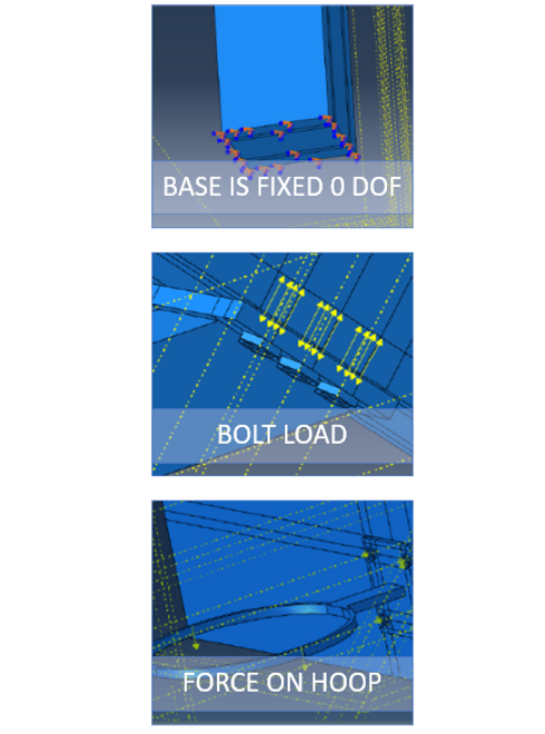
BOUNDARY CONDITIONS
Fixed Boundary conditions: The base of arm1 was kept fixed with all degrees of freedom set to 0
Bolt loads: Bolt loads were applied to all the bolts present in the assembly. A value of 500N was assumed as the bolts are large and would therefore require large amount of torque to fasten.
Additionally, during assembly interaction was provided between the bolt and nut with “tie” type
A series of iterations was performed on the analysis by varying the locations of the applied load.
Case 1 – The Load(2000N) was applied at the very end of the rim attached to the backboard
Case 2- The Load(500N) was applied at the very end of the rim attached to the backboard .
Case 3 - the Load (2000N on each side) was applied at the middle of the rim on either sides. This was chosen as the ideal boundary conditions setup.

ANALYSIS SETUP
MESHING :The mesh was done using a 8-node linear brick elements (linear hexahedral elements) C3D8I, reduced integration, hourglass control. The brick elements were used with incompatible modes. The purpose of using incompatible modes is to improve the bending behaviour of the elements since the expected results will have bending of the rim, backboard, and mounting plate.
Materials used are tempered glass for the backboard and carbon steel for the rest of the system.
RESULTS
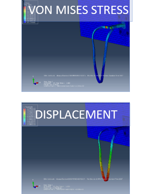
Results for case 1 is as under
When the applied load is 2000N at the very edge of the rim
The Stress diagram showed that the stress was noted to be maximum at the inner side of the ring and backboard attachment. Some amount of stress is also experienced at the connection of the rim and the backboard.
The Von mises diagram for the same is as shown
From the displacement diagram it is clearly evident that the system will fail with a displacement of the edge by 590mm which is unacceptable.
RESULTS
When the load applied at the edge of the rim is 500N
The maximum stress was noted to be 379.5MPa.
And the maximum displacement of the edge of the rim was noted to be 211mm.
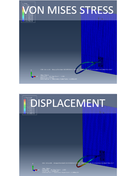
RESULTS
It is observed from the deformation diagram that maximum displacement is observed towards the edge of the rim and is of magnitude 7.883mm.
Additionally, from the von-mises stress diagram we notice that it mimics a cantilever beam and maximum stress is concentrated at the point where the rim meets the backboard. The maximum stress value was found out to be 637.9MPa.

Conclusion
The current design and material considerations for the Hercules Basketball backboard system will fail if used by an NBA player weighing 200lbs . Although a conservative approach ahs been considered in the analysis, it is recommended that either the nature of material is changed, design of connection between the hoop and backboard or design of hoop be changed to prevent failure of the hoop.