VENKATRAGHAVAN
A seasoned mechanical engineering leader with over 6 years of experience, I specialize in transforming innovative concepts into market-ready products. My expertise spans a variety of manufacturing processes, including injection molding, sheet metal fabrication, PCB interconnects, casting, and vacuum forming.
FEA FOR BOLTED NOZZLE OF SATURN V
Structural analysis using ANSYS
The Saturn V's first stage was powered by five F1 engines. analyze the bolted flange joint that connected the mid and lower parts of the F1 engine nozzle. The image below shows a picture of the F1 engine and the corresponding model in ANSYS. Note that the ANSYS model includes only the mid and lower parts of the nozzle and the bolted flange joint connecting them.
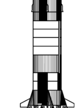
ACTUAL IMAGE OF SATURN V F1 ENGINE
The Saturn V rocket that carried people to the moon is the most powerful machine ever built. Here is the actual image of the part of the Rocket that will be modeled

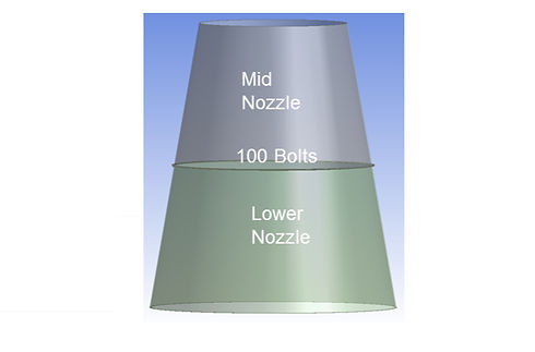
ANSYS MODEL
For Modelling purposes a simplified version of the middle and lower nozzle has been modeled using ANSYS.
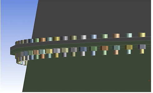
CLOSE UP OF FLANGE
The nozzles are seperated by a flange that is held together using 100 bolts along the circumferance of the flange.
This bolted joint is analysed by building a non-linear finite element model in ANSYS. The main objective is to assess the margin of safety of the flange bolts. The gaps that develop between the jointed parts when the assembly is loaded is also observed.
The pressure due to the exhaust gas in the nozzle is calculated using 1D gas dynamics. It is assumed to vary linearly along the nozzle axis. The pressure at the exit (z=0) is 12.17 psi and the pressure at the entrance to the mid-nozzle is 47.72 psi.

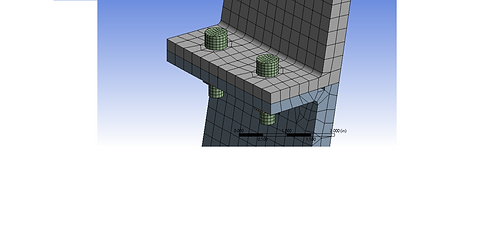
GEOMETRY ON ANSYS
MATERIAL PROPERTIES
The material used for the middle and lower flange is 300 Series stainless steel with
E = 2.9E+7psi, poissons ratio = 0.27 & Coeff of thermal exp = 1E-5 per deg F
The material used for the Bolt and nut is A286 steel with
E = 2.9E+7psi, poissons ratio = 0.31 & Coeff of thermal exp = 9.5E-6 per deg F
MESHING
Implementing a Hex Dominant method to reduce the number of nodes needed and setting the mesh size to 0.3 for the upper and mid flange and 0.075 for the bolt and nut.
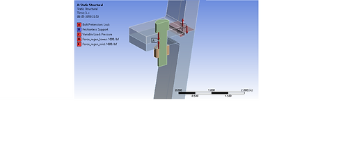
STATIC STRUCTURAL SETTINGS
The Boundary Conditions are given as follows
Frictionless support between middle and lower flange
Bolt pretension between for the bolt
Variable load pressure for the internal pressure forcing the speration of the two nozzle sections
Regeneration fluid pressure
The regeneration channels are omitted in the model. In exchange, a free body diagram is used to deduce the equivalent forces on the mid nozzle and lower nozzle (the upper nozzle is not modeled here). This force pair is modeled as two separate forces, each of 1000 lbf. The gas temperature is 700 F which causes thermal strain. We assume that bolt is pre-loaded to 50% of its breaking strength.
TOTAL DEFORMATION
We run the analysis on only half the bolt and system due to symmetry. The total deformation observed at the final time step is shown here. We can also notice a small gap visible. The max displacement is recorded as 0.0025323 in and min is 5.3257e-6 in.


EQUIVALENT STRESS
We generate the von-mises stress to identify the regions of maximum stress. The maximum stress is located at the shank of the bolt and is approximately 1.4593 E7 psi
However we need to improve the quality of mesh for better results
UPGRADE MESH QUALITY
By removing the hex dominant method, the number of nodes increased from 26,000 to 47,000 nodes. this increases computation time but improves accuracy in results


TOTAL DEFORMATION
The total deformation is observed with a maximum displacement of 0.00015624 in and a min displacement of 5.333E-6 in which is more acceptable
EQUIVALENT STRESS
The von-mises equivalent stress is shown here. the maximum stress observed is 6.1294 E4 psi which is within the permissible limits. However a conserved model has been chosen therefore it is not likely to fail


CONCLUSION
Design improvement suggestions
It can be observed that under 500 times magnification of effects, a gap is observed between the two nozzles. Therefore to reinforce the nozzle interface, the flange can have a larger OD( increase thickness). The flow of regeneration and subsequent fluid pressure does not overcome the bolt load and it is therefore a safe load.
The increase in temperature also causes thermal strain effects which elongates the lower nozzle, however, it is within the design limits.