VENKATRAGHAVAN
A seasoned mechanical engineering leader with over 6 years of experience, I specialize in transforming innovative concepts into market-ready products. My expertise spans a variety of manufacturing processes, including injection molding, sheet metal fabrication, PCB interconnects, casting, and vacuum forming.
Undergraduate design project
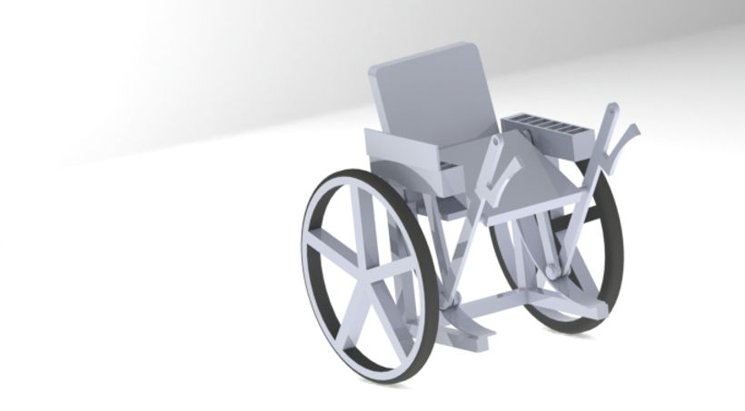
MODIFICATION IN WHEELCHAIR DESIGN
Following is my undergraduate design project wherein my team and I visited a nearby government hospital and performed a survey to gather data regarding the difficulties faced by people using Wheel chairs.
We devised a single mechanism that allows people to get on and off a wheelchair easily.
Design and analysis
DESIGN OF MECHANISM

DIFFERENT LINK ORIENTATIONS
The mechanism basically includes two link whose movements are governed by the force applied on the vertical link in our mechanism. The vertical link also alternatively acts as the brake handle as it allows a person to get into and off the wheelchair while holding the brake simultaneously eliminating the need of a third person.
Areas selected for analysis :
Loading of Arc section in the 2 Link mechanism
Cantilever section on which the seat rests
Hinge about which the seat rotates
The following analysis were carried out in Ansys Workbench with the following assumptions :
Weight of user = 100 Kgs ( Note : The average weight of patients who participated in survey conducted was 70 Kgs. Hence, Factor of Safety = 1.42 )
Material used is Mild Steel

BOUNDARY AND FORCE CONDITIONS FOR ARC
Following is the analysis of the base arc on which the link mechanism lies. A force of 565.5 N is applied at the center of the arc as shown .
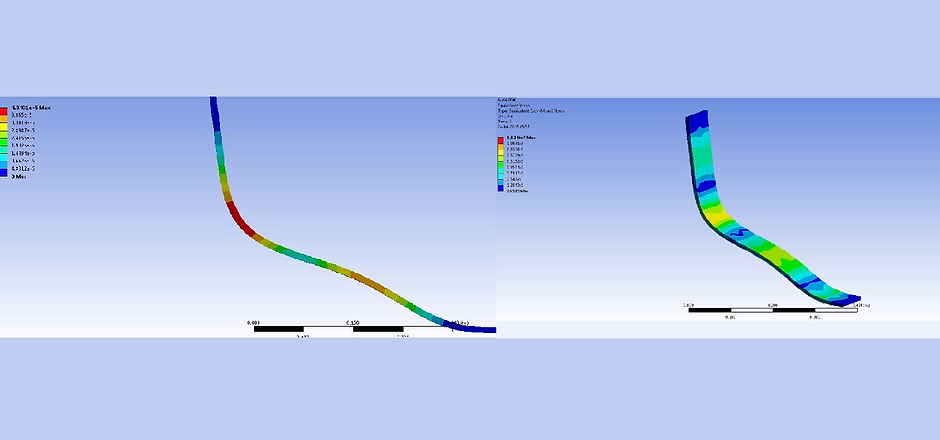
ANALYSIS ON ARC
Deflection ( in meters ) is found to be maximum at the point of application at the center, but is in the order of 10^-3 m. Hence, design is safe
The equivalent Von-mises stress developed in the arc is found to be within the range of 26525 N/mm2 to 1.13e7 N/mm2.

ANALYSIS ON SEAT
The seat is assumed to be a cantilever support and a Uniformly Distributed Load of 490.5 N/m is applied with one end fixed ( where deformation is 0 ). Maximum deformation is in the magnitude of few mm and hence design is safe.

ANALYSIS ON HINGE
Conditions :
Centre Force = 490.5 N
Reaction Force at Fixed support = 620.8 N
A constant shear Force magnitude = 294 N is observed
Maximum bending is observed at the centre ( no support region ) of magnitude 38.86 Nm.